# 填充形状
可以通过多种不同方式填充形状。 在本节中,将了解一般的填充规则,以及可以填充路径的各种方式。
Qt Quick Shapes 提供了两种填充规则,使用ShapePath元素的fillRule属性进行控制。 在下面的截图中显示了不同的结果。 它可以设置成ShapePath.OddEvenFill(奇偶规则),这是默认值,将单独填充路径的每部分,意味着可以创建一个带有孔的形状;另一种规则是ShapePath.WindingFill(环绕数规则),它填充形状上每条水平线上的极端点之间的所有内容(原文:which fills everything between the extreme endpoints on each horizontal line across the shape)。 不管填充规则如何,然后使用笔绘制形状轮廓,因此即使使用缠绕填充规则,轮廓也是在形状内部绘制。(原文:Regardless of the filling rule, the shape outline is then drawn using a pen, so even when using the winding fill rule, the outline is drawn inside the shape.)
译者笔记
这两种规则叫做奇偶规则和非零环绕数规则,具体的解释如下:
- 奇偶规则
如上图所示,如果判断A点是在形状内部还是形状外部? 从A点发出一条射线AC,与形状边的交点分别是c、d,计算交点的个数,偶数表示在形状外边,奇数表示在形状内部,2是偶数,所以在这里表示在形状的外部。如果向另一个方向AD发出射线,会有相同的结果。取B点进行分析,取射线BC,有一个交点d;使用BD方向进行验证,有a、b、c三个交点,可以得到在形状内部的结论。- 非零环绕数规则
如上图所示:取一个绕线的方向1 -> 2 -> 3 -> 4 -> 5,在图上已经绘制出这个方向。
取点A进行分析,取一条从A发出的射线AB,可以看到有c、d两个交点。将AB的一侧当做正值(如:左上角),另一侧认为成负值(右下角)。可以看到最开始的线条是有方向的,c、d都是到负值方向,记为-2。这个最后的值不为0被认为在线条内部。
取点D进行分析,取D远离线形状的方向,明显没有交点,也就是0;取另一个方向(DB)再看看,存在a、b、c、d四个交点,a和b为正值,个数记作+2,c和d为负值,个数为-2,(+2) + (-2)=0。如果和为0表示在形状外面,非0表示在形状里面。
注意:这两种方法分析出来的结果有时候是不同的,例如上面的例子。


下面的示例演示了如何使用上面截图中显示的两个填充规则。
Shape {
    ShapePath {
        strokeWidth: 3
        strokeColor: "darkgray"
        fillColor: "orange"

        fillRule: ShapePath.OddEvenFill

        PathPolyline {
            path: [
                Qt.point(100,  20),
                Qt.point(150, 180),
                Qt.point( 20,  75),
                Qt.point(180,  75),
                Qt.point( 50, 180),
                Qt.point(100,  20),
            ]
        }
    }
}
Shape {
ShapePath {
strokeWidth: 3
strokeColor: "darkgray"
fillColor: "orange"
fillRule: ShapePath.WindingFill
PathPolyline {
path: [
Qt.point(300, 20),
Qt.point(350, 180),
Qt.point(220, 75),
Qt.point(380, 75),
Qt.point(250, 180),
Qt.point(300, 20),
]
}
}
}确定填充规则后,有多种方法可以填充轮廓。 在下面的截图中显示了各种选项,各种选项要么是纯色,要么是Qt Quick提供的三种渐变之一。
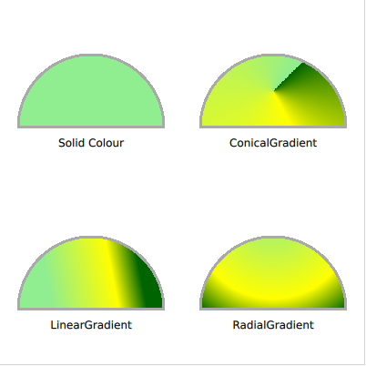
要使用纯色填充形状,请使用ShapePath的fillColor属性,将其设置为颜色名称或编码,然后就使用它填充了形状。
Shape {
    ShapePath {
        strokeWidth: 3
        strokeColor: "darkgray"

        fillColor: "lightgreen"

        startX: 20; startY: 140

        PathLine {
            x: 180
            y: 140
        }
        PathArc {
            x: 20
            y: 140
            radiusX: 80
            radiusY: 80
            direction: PathArc.Counterclockwise
            useLargeArc: true
        }
    }
}如果不想使用纯色,可以使用渐变色,使用ShapePath元素的fillGradient属性应用渐变。
要了解的第一个渐变是LinearGradient,它在起点和终点之间创建线性渐变。 这两端点可以按喜欢的任何方式摆放,例如,创建一个带有角度的渐变。 在两端点之间,可以插入一系列GradientStop(停靠点)元素。 它们被放置在从0.0(即x1, y1位置)到1.0(即x2, y2位置)的position(位置)。 对于每个这样的停靠点,都指定了一种颜色,渐变会在颜色之间柔和地过渡。
提示
如果形状超出端点,则继续使用第一种或最后一种颜色,或者重复渐变或镜像渐变。 此行为是使用LinearGradient元素的spread属性指定。
Shape {
    ShapePath {
        strokeWidth: 3
        strokeColor: "darkgray"

        fillGradient: LinearGradient {
            x1: 50; y1: 300
            x2: 150; y2: 280

            GradientStop { position: 0.0; color: "lightgreen" }
            GradientStop { position: 0.7; color: "yellow" }
            GradientStop { position: 1.0; color: "darkgreen" }
        }

        startX: 20; startY: 340

        PathLine {
            x: 180
            y: 340
        }
        PathArc {
            x: 20
            y: 340
            radiusX: 80
            radiusY: 80
            direction: PathArc.Counterclockwise
            useLargeArc: true
        }
    }
}为了创建一个围绕原点传播的渐变,有点像时钟,使用ConicalGradient(锥形渐变)。 此处,中心点使用centerX和centerY属性指定,起始角度使用angle属性指定。 然后梯度停靠点从给定的角度以顺时针方向展开360度。
Shape {
    ShapePath {
        strokeWidth: 3
        strokeColor: "darkgray"

        fillGradient: ConicalGradient {
            centerX: 300; centerY: 100
            angle: 45

            GradientStop { position: 0.0; color: "lightgreen" }
            GradientStop { position: 0.7; color: "yellow" }
            GradientStop { position: 1.0; color: "darkgreen" }
        }

        startX: 220; startY: 140

        PathLine {
            x: 380
            y: 140
        }
        PathArc {
            x: 220
            y: 140
            radiusX: 80
            radiusY: 80
            direction: PathArc.Counterclockwise
            useLargeArc: true
        }
    }
}为了创建一个圆形的渐变,有点像水面上的环,使用了RadialGradient。 为它指定两个圆,焦点圆和中心圆,渐变停靠点是从焦点圆到中心圆。在这些圆之外,spread属性指定最后一种颜色是继续、镜像或是重复。
Shape {
    ShapePath {
        strokeWidth: 3
        strokeColor: "darkgray"

        fillGradient: RadialGradient {
            centerX: 300; centerY: 250; centerRadius: 120
            focalX: 300; focalY: 220; focalRadius: 10

            GradientStop { position: 0.0; color: "lightgreen" }
            GradientStop { position: 0.7; color: "yellow" }
            GradientStop { position: 1.0; color: "darkgreen" }
        }

        startX: 220; startY: 340

        PathLine {
            x: 380
            y: 340
        }
        PathArc {
            x: 220
            y: 340
            radiusX: 80
            radiusY: 80
            direction: PathArc.Counterclockwise
            useLargeArc: true
        }
    }
}
提示
高级用户可以使用片段着色器来填充形状。 这样,就可以完全自由地选择如何填充形状。 有关着色器的更多信息,请参见特效一章。